How much power can you generate with a hydroelectric turbine?
These micro-hydro turbines require that water be piped from a higher elevation to a lower elevation where the turbine is installed. This pipeline is called a “penstock” and the elevation difference is called the “static head”. The “dynamic head” is the static head adjusted for losses due to friction in the pipeline The amount of power produced depends on the dynamic head, the amount of water flow and the efficiency of the turbinegenerator combination. To get an idea of the potential power generation in watts, multiply the dynamic head in feet, times flow in gallons per minute, times 0.18, times turbine efficiency. Turbine efficiency ranges from 35% to 70%, with higher efficiency at higher heads. To get a rough idea, use 0.40 (representing 40%) as a multiplier for efficiency.
Dynamic Head (ft) x Flow (gpm) x 0.18 x Turbine Efficiency (use 0.40) = Output watts
Water flows greater than a single micro hydro turbine can handle can be accommodated by using multiple turbines with a penstock manifold, or separate penstocks running to each unit. The Harris Pelton turbines use a brushless alternator and a Pelton wheel runner, and are well suited to higher head and water flows up to 250 gpm. Flow is limited by nozzle size. The Harris permanent magnet (PM) alternator provides up to 50% efficiency and is adjustable for tuning to the particular site conditions. The HI-Power LV Hydroelectric Generator can deliver up to 1500 watts into 12, 24, or 48V battery banks. The LV is also available with a 120V output for wire runs as long as 1000 feet and is a good solution where the generator must be far from the batteries. Transmitting the power from the generator to the battery at twice the battery voltage allows you to use 1/4 of the wire size for the same power loss. At 4 times the battery voltage, you can use 1/16 of the wire size required to transmit power at the battery voltage. An Iota battery charger (page 161) or the new MidNite Classic MPPT charge controller (page 125) is used to convert this high voltage down to the battery’s voltage, at the battery’s location The HI-Power LV 120V unit can also be used with a PV Powered inverter for grid-tie applications without batteries. Call for more information on grid-tie micro-hydro applications.
Pipelines
A hydroelectric turbine uses the energy from the pressure at the end of a gravity-fed pipeline. This pressure, usually measured in pounds per square inch (psi), is directly related to the head: the vertical drop from the top of the pipeline, where the water enters the system, to the turbine located at the bottom of the pipeline. The pressure at the lowest point of a pipeline is equal to 0.433 times the head, (the vertical distance in feet).
Pressure is a determining factor in how much power is available and what type of pipe is required. Polyethylene pipe can be used for pressures up to 100 psi, PVC pipe is available with pressure ratings from 160 to 350 psi and steel pipe can withstand 1000 psi or more. Check with your local plumbing supplier for pipe ratings. Pipe diameter is very important. All pipelines will cause the water flowing in them to lose some energy to friction. The pipe must be large enough for the maximum quantity of water it will carry.
The pressure at the bottom of a pipeline when water is not flowing is called static pressure. When water is flowing through the outlet or nozzle of the hydroelectric turbine, the pressure at the outlet is the dynamic pressure or running head. If you install a gate valve on the pipeline just above the turbine and a pressure gauge on a "T" fitting just above the gate valve, you will read the static pressure on the gauge when the valve is closed and the dynamic pressure when the valve is opened. The maximum power that can be delivered by a pipeline will occur when the dynamic pressure is approximately 2/3 of the static pressure.
The actual flow rate of the water in a hydroelectric system is determined by the diameter of the nozzle. We will supply a turbine with the proper size nozzle for your site, depending on the head, flow, length and diameter of the pipe. We carry hydroelectric generators made by HI-Power Hydroelectric and Harris Hydroelectric. Use the descriptions on the following pages to help determine which turbine will work best for your site and power requirements.
We can help you design your system
If you think you have a suitable site, contact us and we will help you choose the best unit for your situation. Please provide the following information about your site:
1. Head – The total vertical elevation from the place where the water enters the pipe to the point where the turbine will be located.
2. Flow – The number of gallons per minute that are available.
3. Distance – The length of pipe that will be necessary to carry the water from the pickup to the turbine. If the pipe is already installed, what is the type and diameter?
4. Location – Distance from turbine to batteries.
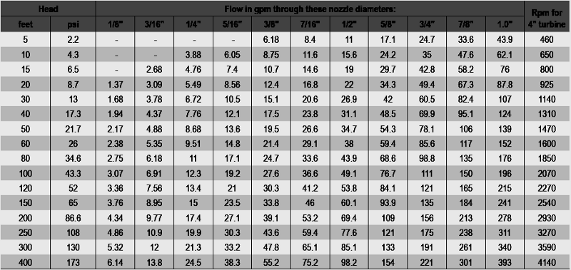
Nozzle selection
Power output of a hydroelectric generator is determined by the pressure of the water at the nozzle and the amount of water flowing out of the nozzle. The larger the nozzle, the greater the flow will be. The nozzle must also be sized small enough to keep your pipeline full and keep the speed of the water in the pipe below 5 feet per second. The nozzle selection table on the next page shows water flow through various size nozzles at given pressures. Use this table to determine what size nozzle and how many nozzles you need to accommodate the flow of water you have and to deliver the amount of power you need. A pressure gauge in the pipe feeding your turbine, installed before the shutoff valve, can help you check proper operation and diagnose problems. When the valve is shut off, the gauge will read the static pressure in pounds per square inch psi (head in feet x 0.433). When the valve is turned on the gauge will read a lower (dynamic) pressure. The difference between these two pressures represents your loss to friction in the pipe. The greater the flow, the greater your loss will be.
Water Flow Information for Pumping and Hydroelectric Design
Flow Through Nozzles
The table below shows the flow in gallons per minute (gpm) through various diameter nozzles at a range of heads from 5 feet to 400 feet. Use table to choose what nozzle size to use and how many nozzles a turbine must have to give the required flow to use all of the water available in the system.
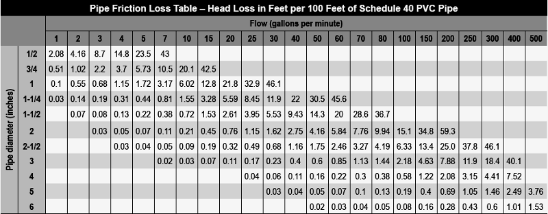
 PVC Pipe Loss Table
Use the table below to determine what pipe size is required to efficiently allow necessary flow for your power need. Once you know the required flow for your system (gpm), find the head loss for various pipe sizes. Multiply the head loss number by the length of the pipe divided by 100 and you will get the loss of head for that pipe size. The actual head minus the head loss will give you the effective dynamic head in the system.